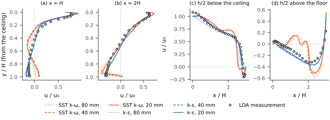
cfd.turbulence_model | kEpsilon | - | | Chosen from the IEA Annex 20 2-D isothermal validation (results/cfd/annex20.md): with the habitat cases' wall functions and schemes, standard k-epsilon reproduced the measured floor return flow and ceiling-jet separation that kOmegaSST missed, at every mesh tested. Isothermal evidence only (the buoyant Annex 20 case has no data). Runs built before 2026-10-13 15:00 used kOmegaSST (their case files and ledger digest record it). User decision 2026-10-13. |
container.length_discrepancy_placement | door end | - | yes | Fig 2 length (464 in = 11785.6 mm) is 246.4 mm shorter than the steel interior (12032 mm). Unexplained (end framing? door-end wall?); the gap is placed at the door end for the exterior shell only. |
container.lining.ceiling | 0.0 | mm | yes | As lining.floor; clear height therefore taken as the steel interior height. |
container.lining.floor | 0.0 | mm | yes | No floor build-up is stated. The Fig 2 width (92 in = 2336.8 mm) is within 15 mm of the bare steel width (2352 mm), suggesting little or no lining. |
container.roof_thickness | 40.0 | mm | | The spec gives only external (2896) and internal (2698) heights; the 198 mm difference is split as roof panel + roof rails (this value) and floor structure (the remainder). Affects only the exterior shell, not the CFD domain. |
crew.body_box | [0.4, 0.25] | m | | Standing crewmember represented as a 1.75 m tall box of this plan size (width x depth) carrying the BVAD sources; body shape not modelled in M0. |
fpm.attic.is_full_height_compartment | True | - | yes | Figs 4-5 renders draw the 40 in attic as a full-height end compartment behind a partition (not a loft); the CFD domain therefore stops at the partition. |
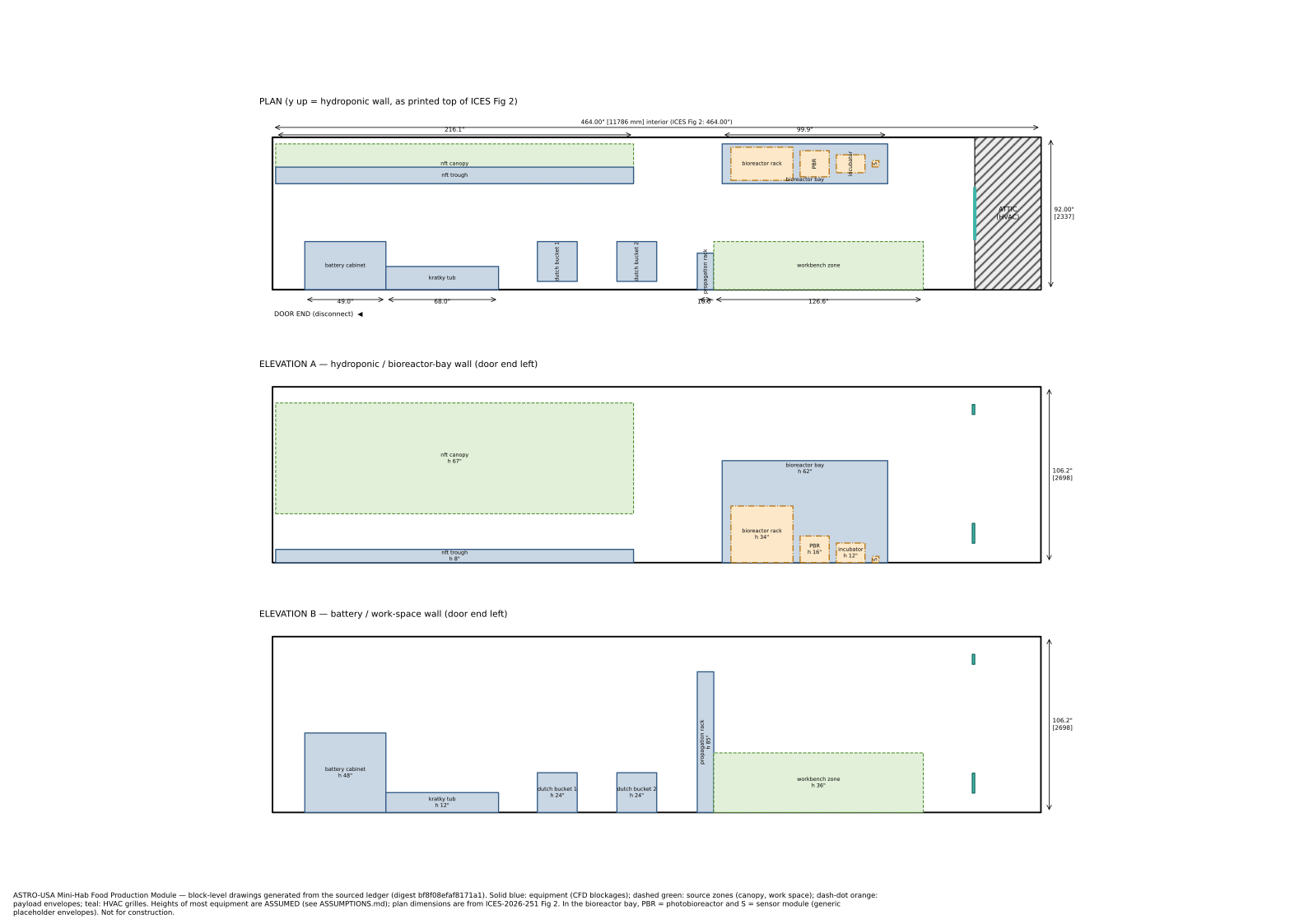
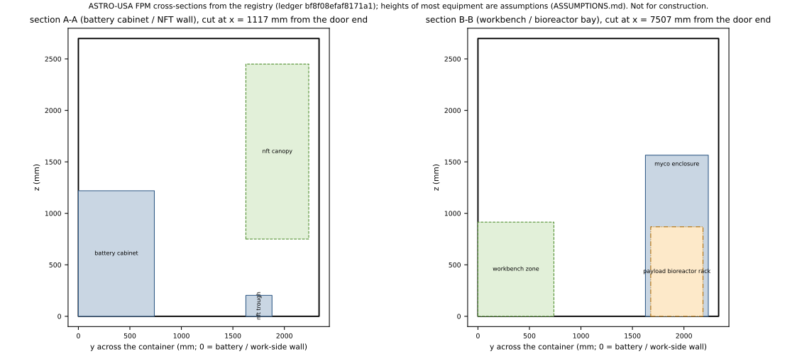
fpm.battery_cabinet.height | 48.0 | in | yes | Fig 2 gives only the 49 x 29 in footprint; Fig 5 shows a 4 x 4 wall-mounted battery array. Modelled as a floor cabinet of assumed height. |
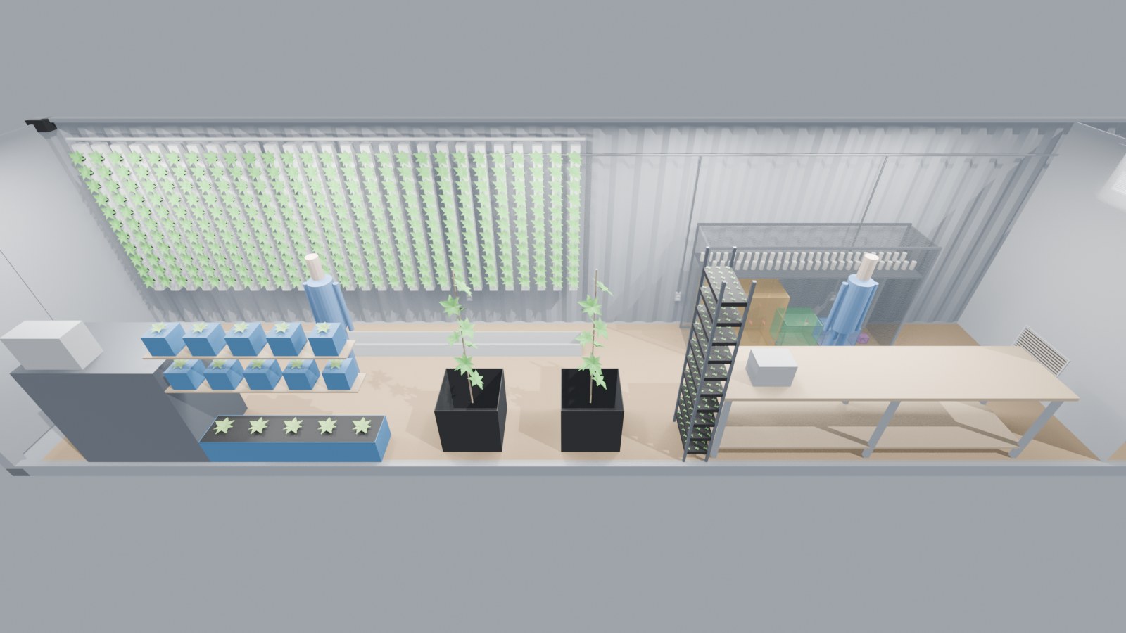
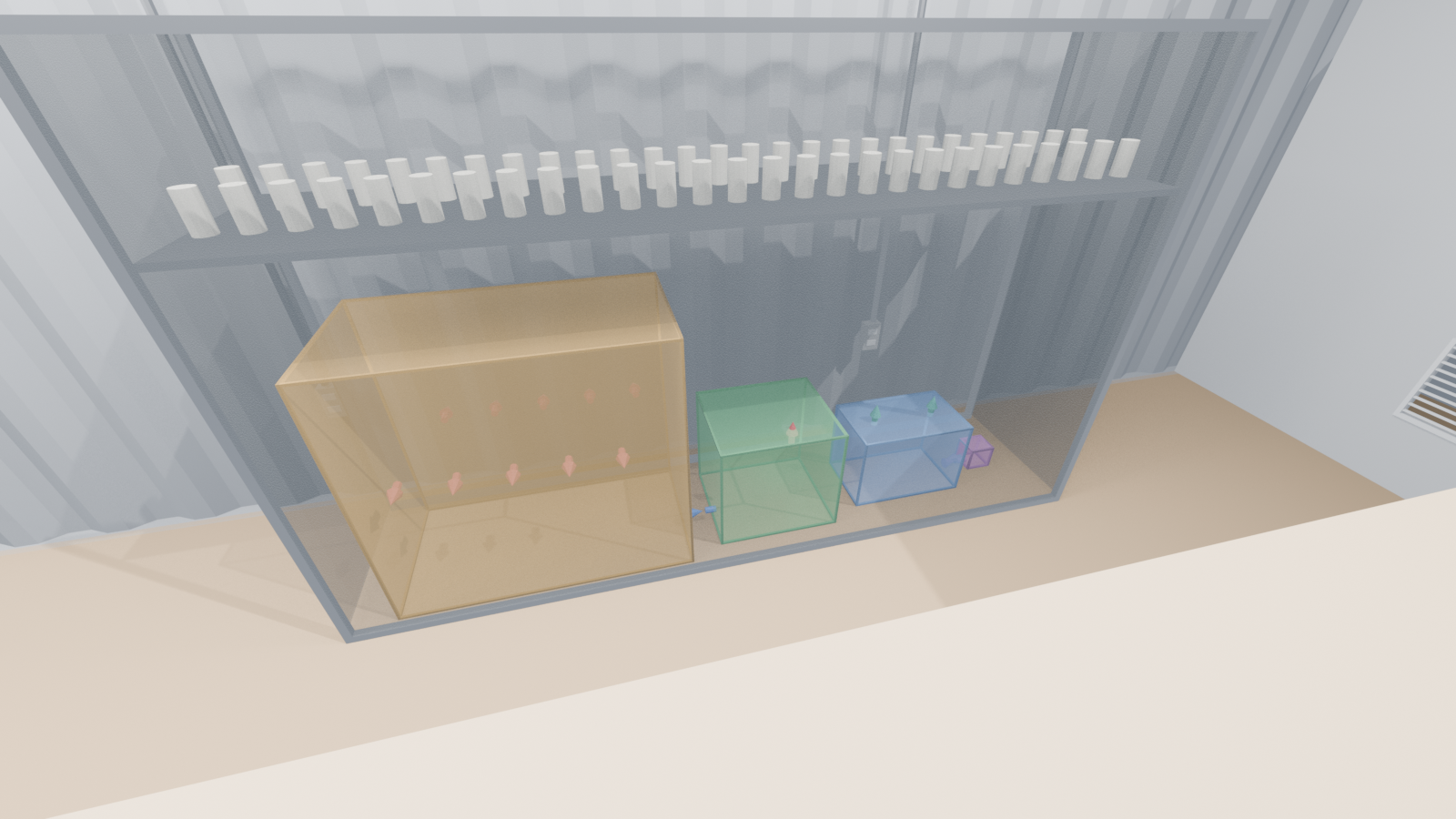
fpm.bay.enclosure_height_fraction | 0.58 | - | yes | Bioreactor bay (the zone labelled Mycoponics in ICES-2026-251 Fig 2). Fig 4 render: floor-standing transparent enclosure roughly 55-60 % of wall height; not dimensioned. |
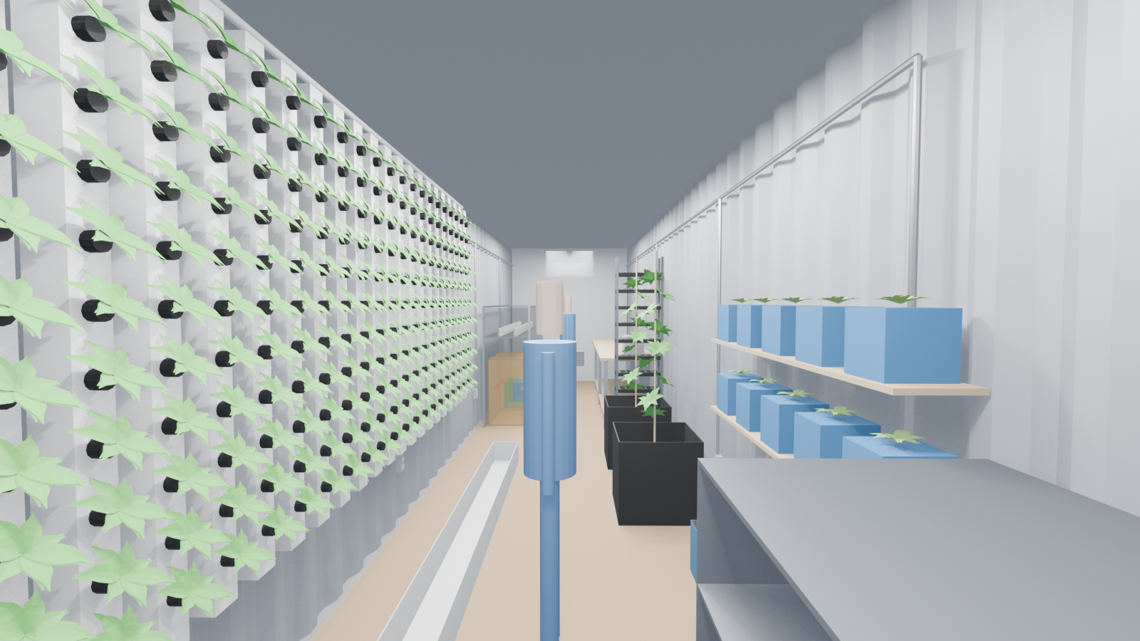
fpm.dutch_buckets.height | 24.0 | in | yes | Fig 5 render draws the buckets as cubes on the 24 x 24 in Fig 2 footprint. |
fpm.electrical.heat_split | {'hydroponics': 0.5, 'propagation': 0.2, 'bat | fraction of load_average | yes | The paper gives total load only. M0 smoke-test split across the powered zones (pumps/lights at the NFT wall and propagation rack, inverter/charger losses at the battery cabinet, sensor computer at the bench) until the team supplies the equipment list. |
fpm.hydroponics.canopy_z_bottom | 0.75 | m | yes | Fig 4 render shows the 11 planting rows occupying roughly the upper two-thirds of the wall above a floor trough; lowest row height not stated. |
fpm.hydroponics.canopy_z_top | 2.45 | m | yes | Fig 4 render: top planting row just below the ceiling (interior height 2.698 m); exact height not stated. |
fpm.hydroponics.trough_depth | 10.0 | in | yes | As trough_height; placed against the front edge of the 24 in hydroponics band. |
fpm.hydroponics.trough_height | 8.0 | in | yes | Fig 4 render shows a low floor-level collection trough along the hydroponic wall; its size is not dimensioned. |
fpm.kratky.floor_tub_height | 12.0 | in | yes | Fig 5 render shows a low rectangular floor tub; height not dimensioned. |
fpm.propagation.height_fraction | 0.8 | - | yes | Fig 5 render: the ten-level rack reaches roughly four-fifths of wall height; not dimensioned. |
fpm.workbench.top_height | 36.0 | in | yes | Fig 5 render shows a bench in the work space; height not stated. Common standing-bench height assumed. |
payloads.bioreactor_rack.co2_per_tube | 1.82 | g/day | yes | Planning value for the CO2 released by one small fungal or microbial culture vessel; not a measured rate. |
payloads.bioreactor_rack.envelope | [951.0, 507.6, 869.0] | mm | yes | Representative outer envelope of a benchtop rack of ten tubular bioreactor vessels (5 x 2), placeholder until the team chooses the hardware. |
payloads.bioreactor_rack.heat | 0.0 | W | yes | No heat budget for the placeholder rack; any pumps, lighting or sterilisation hardware would add to it. |
payloads.bioreactor_rack.vent_flow | 0.35 | L/min | yes | Planning value for the headspace sweep that carries each vessel's off-gas out through its vent. |
payloads.incubator.envelope | [440.0, 275.0, 300.0] | mm | yes | Representative outer envelope of a benchtop germination / microgreen incubator, placeholder until the team chooses the hardware. |
payloads.incubator.heat | 0.0 | W | yes | No heat budget for the placeholder incubator. |
payloads.layout.frame_clearance | 25.0 | mm | | Inside clearance to the enclosure frame posts (matches the VR frame section). |
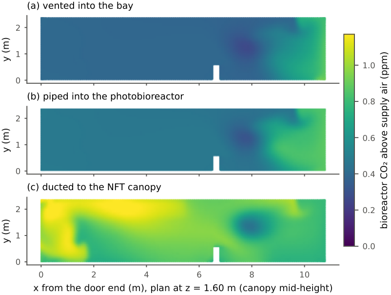
payloads.layout.offgas_route | bay | - | yes | Where the bioreactor vents' off-gas goes is a design choice (into the bay -> room air, into the photobioreactor's sparger, or ducted to the NFT wall). Default: vented into the bay; scenario S6 compares the routes. |
payloads.layout.order | ['bioreactor_rack', 'photobioreactor', 'incub | - | yes | Illustrative arrangement along the bay from the door end: the photobioreactor beside the bioreactor rack (so it can take the rack's off-gas), then the incubator and the sensor module; spaced evenly. Not a team decision. |
payloads.layout.rotation_deg | {'bioreactor_rack': 0, 'photobioreactor': 180, &#x | deg | yes | Rotation of each payload about its own vertical axis. The photobioreactor is turned 180 deg so its gas inlet (its +x face) faces the bioreactor rack beside it. |
payloads.photobioreactor.co2_uptake | 0.0 | g/day | | CO2 fixation by the algal culture is not modelled yet (no rate for the placeholder). |
payloads.photobioreactor.envelope | [446.0, 400.0, 408.3] | mm | yes | Representative outer envelope of a benchtop algae photobioreactor, placeholder until the team chooses the hardware. |
payloads.photobioreactor.led_power | 16.4 | W | yes | Placeholder electrical power of the culture's LED panel at full output, all of it treated as heat to the room. |
payloads.photobioreactor.sparge_flow_max | 1.8 | L/min | yes | Placeholder maximum gas flow of the sparging pump; sets how many bioreactor vents it can take in the S6 route that pipes off-gas into it. |
payloads.ports.bioreactor_rack.envelope_check | [951.0, 507.6, 869.0] | mm | yes | Illustrative port layout: one headspace vent per vessel on the rack's front face, at mid-height of the vessels; each carries the ledger's per-vessel vent flow and CO2. |
payloads.ports.bioreactor_rack.vent_r0c0 | {'name': 'vent_r0c0', 'kind': 'gas_ | mm | yes | Illustrative port layout: one headspace vent per vessel on the rack's front face, at mid-height of the vessels; each carries the ledger's per-vessel vent flow and CO2. |
payloads.ports.bioreactor_rack.vent_r0c1 | {'name': 'vent_r0c1', 'kind': 'gas_ | mm | yes | Illustrative port layout: one headspace vent per vessel on the rack's front face, at mid-height of the vessels; each carries the ledger's per-vessel vent flow and CO2. |
payloads.ports.bioreactor_rack.vent_r0c2 | {'name': 'vent_r0c2', 'kind': 'gas_ | mm | yes | Illustrative port layout: one headspace vent per vessel on the rack's front face, at mid-height of the vessels; each carries the ledger's per-vessel vent flow and CO2. |
payloads.ports.bioreactor_rack.vent_r0c3 | {'name': 'vent_r0c3', 'kind': 'gas_ | mm | yes | Illustrative port layout: one headspace vent per vessel on the rack's front face, at mid-height of the vessels; each carries the ledger's per-vessel vent flow and CO2. |
payloads.ports.bioreactor_rack.vent_r0c4 | {'name': 'vent_r0c4', 'kind': 'gas_ | mm | yes | Illustrative port layout: one headspace vent per vessel on the rack's front face, at mid-height of the vessels; each carries the ledger's per-vessel vent flow and CO2. |
payloads.ports.bioreactor_rack.vent_r1c0 | {'name': 'vent_r1c0', 'kind': 'gas_ | mm | yes | Illustrative port layout: one headspace vent per vessel on the rack's front face, at mid-height of the vessels; each carries the ledger's per-vessel vent flow and CO2. |
payloads.ports.bioreactor_rack.vent_r1c1 | {'name': 'vent_r1c1', 'kind': 'gas_ | mm | yes | Illustrative port layout: one headspace vent per vessel on the rack's front face, at mid-height of the vessels; each carries the ledger's per-vessel vent flow and CO2. |
payloads.ports.bioreactor_rack.vent_r1c2 | {'name': 'vent_r1c2', 'kind': 'gas_ | mm | yes | Illustrative port layout: one headspace vent per vessel on the rack's front face, at mid-height of the vessels; each carries the ledger's per-vessel vent flow and CO2. |
payloads.ports.bioreactor_rack.vent_r1c3 | {'name': 'vent_r1c3', 'kind': 'gas_ | mm | yes | Illustrative port layout: one headspace vent per vessel on the rack's front face, at mid-height of the vessels; each carries the ledger's per-vessel vent flow and CO2. |
payloads.ports.bioreactor_rack.vent_r1c4 | {'name': 'vent_r1c4', 'kind': 'gas_ | mm | yes | Illustrative port layout: one headspace vent per vessel on the rack's front face, at mid-height of the vessels; each carries the ledger's per-vessel vent flow and CO2. |
payloads.ports.incubator.envelope_check | [440.0, 275.0, 300.0] | mm | yes | Illustrative port layout: an intake and an exhaust fan in the incubator's hood, blowing upward; fan flow not set. |
payloads.ports.incubator.exhaust_fan | {'name': 'exhaust_fan', 'kind': 'fa | mm | yes | Illustrative port layout: an intake and an exhaust fan in the incubator's hood, blowing upward; fan flow not set. |
payloads.ports.incubator.intake_fan | {'name': 'intake_fan', 'kind': 'fan | mm | yes | Illustrative port layout: an intake and an exhaust fan in the incubator's hood, blowing upward; fan flow not set. |
payloads.ports.photobioreactor.envelope_check | [446.0, 400.0, 408.3152] | mm | yes | Illustrative port layout: a gas inlet on the +x face (for off-gas piped from the bioreactor rack) and a vent on the top of the culture vessel. |
payloads.ports.photobioreactor.gas_in | {'name': 'gas_in', 'kind': 'gas_in& | mm | yes | Illustrative port layout: a gas inlet on the +x face (for off-gas piped from the bioreactor rack) and a vent on the top of the culture vessel. |
payloads.ports.photobioreactor.vent | {'name': 'vent', 'kind': 'gas_out&# | mm | yes | Illustrative port layout: a gas inlet on the +x face (for off-gas piped from the bioreactor rack) and a vent on the top of the culture vessel. |
payloads.ports.sensor_module.envelope_check | [104.0, 96.0, 96.0] | mm | yes | Illustrative port layout: a sample inlet and outlet on the -x face of the sensor module; a small pump draws room air through and returns it. |
payloads.ports.sensor_module.sample_in | {'name': 'sample_in', 'kind': 'samp | mm | yes | Illustrative port layout: a sample inlet and outlet on the -x face of the sensor module; a small pump draws room air through and returns it. |
payloads.ports.sensor_module.sample_out | {'name': 'sample_out', 'kind': 'sam | mm | yes | Illustrative port layout: a sample inlet and outlet on the -x face of the sensor module; a small pump draws room air through and returns it. |
payloads.sensor_module.envelope | [104.0, 96.0, 96.0] | mm | yes | Representative outer envelope of a small pumped gas-sampling sensor module, placeholder until the team chooses the hardware. |
payloads.sensor_module.heat | 0.0 | W | | A small battery sensor module is taken as a negligible heat source. |
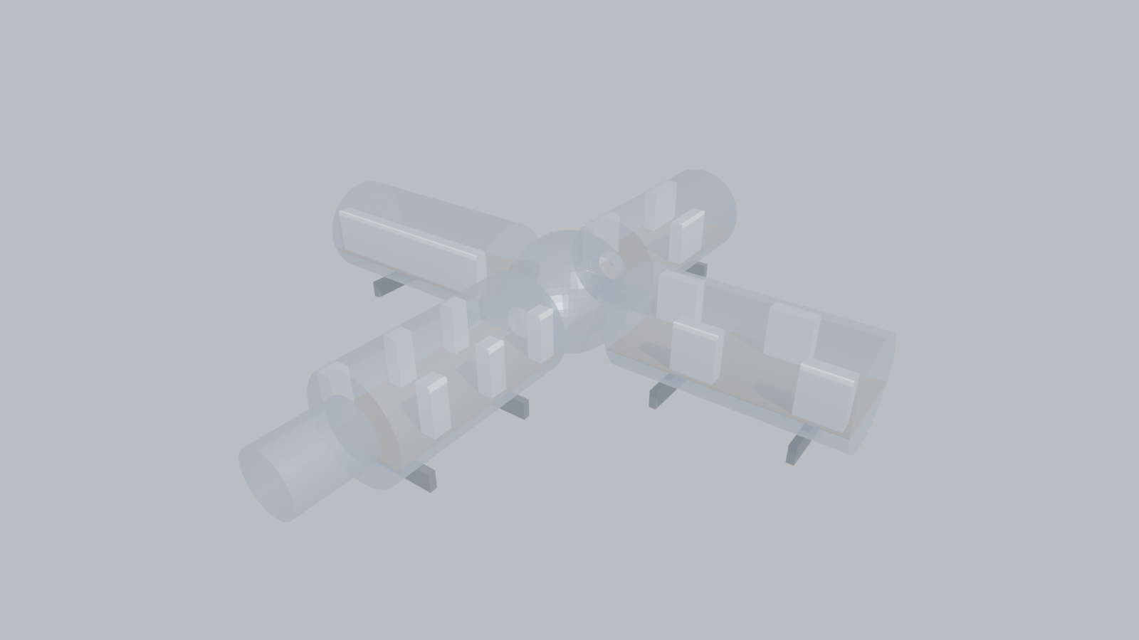
primary.airlock | {'diameter': 2.4, 'length': 3.0} | m | yes | Concept airlock cylinder on the node (Fig 1: vacuum pump, air pump, pressure sensors). Excluded from NHV, as in the NHV guideline. |
primary.crew | 6 | - | yes | The paper sizes the Mini-Hab for a crew of six; the primary habitat's crew size is not stated. Six also matches the NHV guideline's assumption. |
primary.deck_below_axis | 0.6 | m | yes | Floor deck height in the horizontal cylinders, below the module axis (gives ~2.6 m headroom on the centre line of a 4.0 m inner diameter). |
primary.habitable_fraction | [0.4, 0.5, 0.6] | - | yes | NHV is pressurised volume minus equipment, stowage and systems; it can only be measured from a real internal layout. A low / central / high fraction of the internal pressurised volume (airlock excluded) brackets it. |
primary.hatch_tunnel | {'diameter': 1.3, 'length': 0.6} | m | yes | Short hatch tunnel (berthing length) between the node and each module. Modules start beyond the node surface, so perpendicular modules clash only if a module is wider than the node; the generator checks for clashes. |
primary.modules | [{'name': 'crew', 'diameter': 4.2, ' | m | yes | Concept: four radial cylinders on the node, with the systems of the paper's Fig 1 grouped by function. Diameters and lengths are study variables (a ~4 m class is ISS-like and road-transportable as an oversize load; not checked against any transport rule). |
primary.node | {'diameter': 5.0} | m | yes | Concept: one spherical hub node joining the modules (ISS-like topology). Diameter is a study variable. |
primary.wall_thickness | 0.1 | m | yes | Shell + insulation + liner allowance between outer and inner diameter. Material not selected. |
scenario_m0.crew_on_duty | 2 | - | yes | Smoke test: two crewmembers working (one at the NFT wall, one at the bench). |
scenario_m0.crew_x | [110.0, 330.0] | in | | Crew positions along the length (Fig 2 frame): in front of the hydroponics and at the work space. |
scenario_m0.hvac.return_grille | [24.0, 12.0] | in | yes | Return grille (width x height) low on the attic partition; size and position unknown. |
scenario_m0.hvac.return_grille_center_z | 0.45 | m | yes | Return low on the partition. |
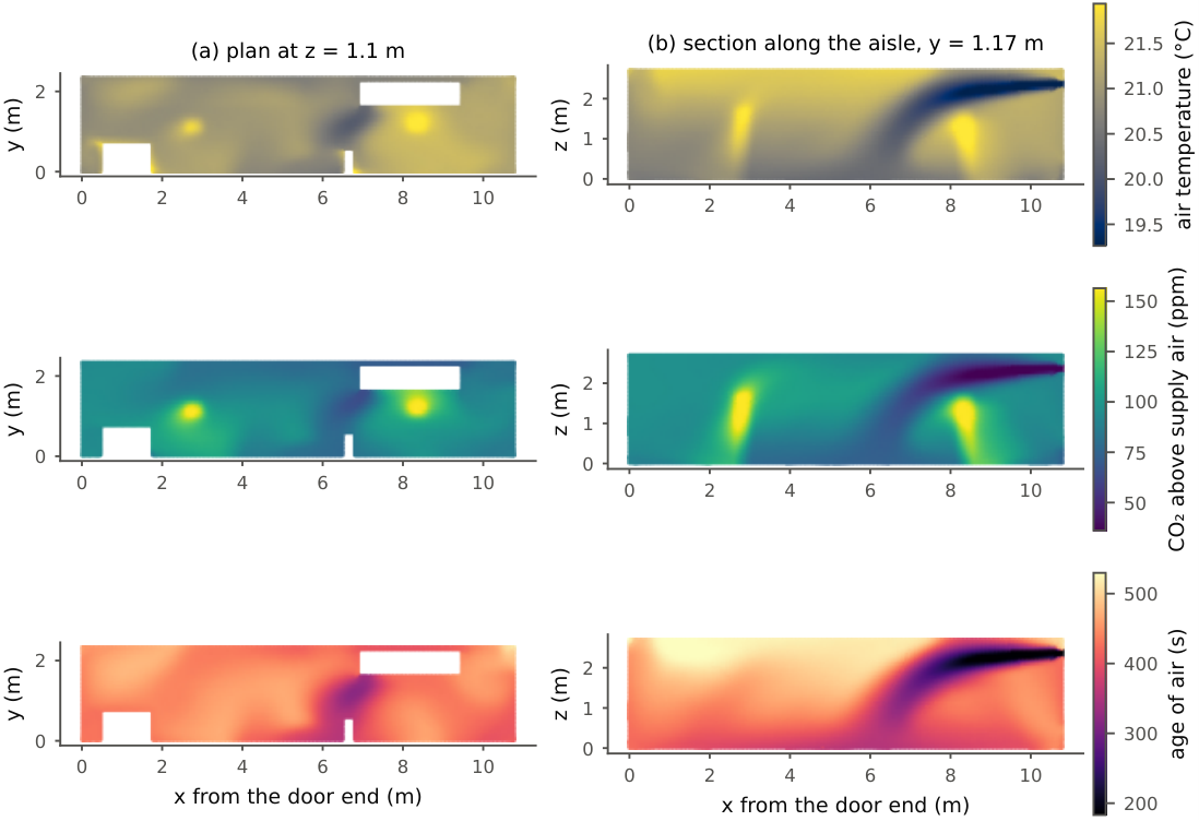
scenario_m0.hvac.setpoint_T | 24.0 | C | yes | Initial room temperature; BVAD Table 3-23 inputs use a 297.2 K (24.05 C) cabin. |
scenario_m0.hvac.supply_T | 18.0 | C | yes | Placeholder coil-leaving temperature for the smoke test. |
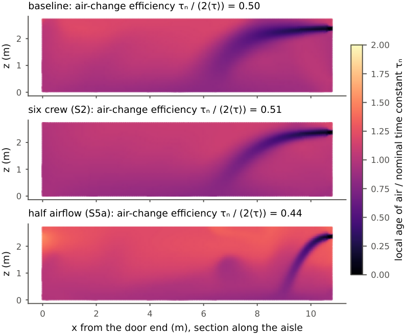
scenario_m0.hvac.supply_flow | 300.0 | cfm | yes | Unknown attic unit; a small ductless split delivers a few hundred cfm. Placeholder until the unit is known; S5 screens the sensitivity. |
scenario_m0.hvac.supply_grille | [30.0, 6.0] | in | yes | Supply grille (width x height) high on the attic partition; size and position unknown. |
scenario_m0.hvac.supply_grille_center_z | 2.35 | m | yes | Supply high on the partition (split-type head). |
scenario_m0.payloads_powered | False | - | | M0 smoke test keeps the payloads unpowered so its heat total (520 W) is unchanged; the payload-siting scenario (S6) switches them on. |
scenario_m0.walls_adiabatic | True | - | | M0 smoke test only: all heat leaves through the HVAC. U-value walls with sol-air temperatures arrive in M2. |
scenario_s2.crew_on_duty | 6 | - | yes | Peak occupancy: the paper sizes the Mini-Hab food supply for a crew of six; S2 puts all six in the FPM at once as an upper bound on crew heat, CO2 and water vapour. |
scenario_s2.crew_x | [40.0, 110.0, 180.0, 250.0, 330.0, 390.0] | in | yes | Six standing crewmembers spread along the aisle (Fig 2 frame), one every ~60-80 in, clear of the attic partition. |
scenario_s3.crew_cases | [2, 6] | - | | The M0 working crew and the S2 peak occupancy. |
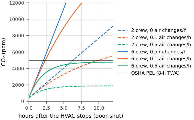
scenario_s3.infiltration_ach | [0.0, 0.1, 0.5] | 1/h | yes | Air changes per hour through the closed container's seals and penetrations: unknown, so swept from sealed (worst case) to leaky. Measure with a CO2 decay test. |
scenario_s5a.hvac.supply_flow | 150.0 | cfm | | S5 sensitivity screen: half the M0 placeholder flow (300 cfm), supply temperature unchanged. |
scenario_s5b.hvac.supply_flow | 600.0 | cfm | | S5 sensitivity screen: twice the M0 placeholder flow (300 cfm), supply temperature unchanged. |
scenario_s6.bioreactor_rack_open | True | - | | The rack is an open frame: 10 tubes (~0.105 m3) fill ~27 % of its 0.391 m3 envelope, below the 0.6 fill fraction above which a part is modelled as a solid (review item 10). The model carries envelopes only, so the tubes are not drawn. |
scenario_s6.enclosure_open | True | - | yes | The bioreactor bay enclosure's walls, doors and ventilation are not described (Fig 4 shows a transparent box). With a solid block nothing inside it could exchange air, so S6 treats the bay as open to the room: an upper bound on mixing out of the bay. |
scenario_s6.payloads_powered | True | - | | S6 runs the payloads: the photobioreactor's LED heat and the bioreactor rack's off-gas CO2 are switched on. |
scenario_s6.routes | ['bay', 'photobioreactor', 'nft_wall'] | - | yes | Candidate off-gas routes: (1) each vessel vent releases into the bay; (2) piped to the photobioreactor's sparger up to its maximum flow, the remaining vessels venting into the bay, culture uptake taken as zero (no rate for the placeholder), so the CO2 leaves at its vent; (3) ducted to the NFT canopy and released evenly through it. |
sensors.exclusion_layers | ['plants', 'water', 'payloads'] | - | | Registry layers whose parts exchange gas or humidity with the air in reality but not (or not fully) in the current CFD. |
sensors.exclusion_margin | 0.3 | m | | Candidates within this distance of a plant, water-culture, bioreactor-bay or payload part are dropped: plant and fungal gas exchange is not modelled yet (the canopy carries LED heat only), so the CFD would wrongly rate a sensor in or beside a canopy as representative of the room, whereas in reality it would read the plants. |
sensors.mount_heights | [1.2, 1.5] | m | yes | Candidate wall-mount heights: seated and standing breathing height, both reachable for maintenance. |
sensors.occupied_zone_z | [0.1, 1.8] | m | | Height band the crew occupy and breathe in (standing crew, 1.75 m tall in the crew ledger); the reference each candidate sensor is scored against is the volume mean over this band. |
sensors.spacing | 0.25 | m | | Spacing of candidate positions along each wall; positions that fall inside equipment are dropped. |
sensors.wall_offset | 0.05 | m | | Sensor sampling point this far off the wall lining (housing depth). |
site.crew_layout | [{'item': 'bunk stack (2 berths)', 'wall' | m | yes | Concept berthing for the paper's crew of six (two-week mission): three two-berth stacks, lockers and a table. Illustrative only; galley, hygiene and medical spaces of Fig 1 are not yet placed. |
site.lab_layout | [{'item': 'sink + eyewash', 'wall': � | m | yes | Concept arrangement of the equipment listed for the Lab and Work Area and the waste-management bioreactor train in Fig 1 (Year-2 Laboratory Module, BSL-2 intent). Positions and sizes are illustrative proportions for discussion only. |
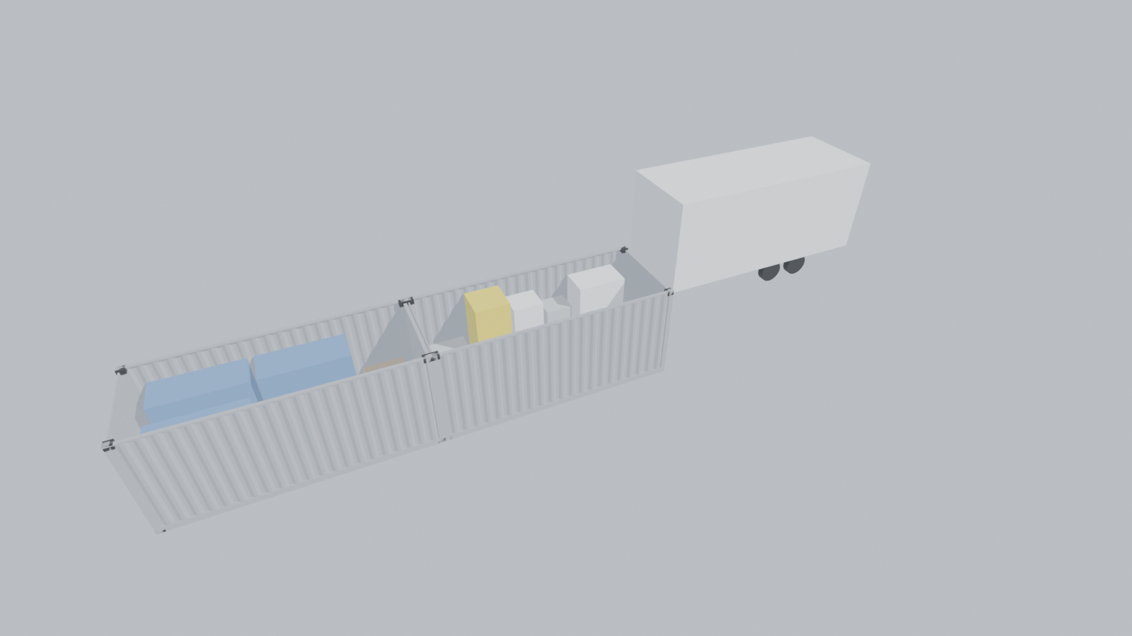
site.module_container | 20 ft standard dry | - | yes | Fig 10 draws the Laboratory and Crew Quarters modules at roughly half to two-thirds of the FPM's length; a 20 ft container is the nearest standard unit. Not stated in the paper. |
site.row_gap | 0.0 | m | yes | Fig 10 draws the rows touching. A real site would leave access space between modules; replace with the planned spacing. |
site.trailer.height | 3.5 | m | yes | Placeholder enclosed-trailer height; replace from ICES-2026-290 or the trailer itself. |
site.trailer.width | 2.59 | m | yes | Trailer dimensions are in ICES-2026-290 (not available); 102 in (2.59 m) is the usual US road-legal trailer width, used as a placeholder. |
vr.battery_block | [12.0, 6.8, 9.0] | in | yes | Visual only: 16 x 12 V batteries (Fig 6) drawn as generic 12 V blocks (L x W x H); chemistry and model unknown. |
vr.conduit_height | 2.35 | m | | Visual only: Fig 8 shows circuits running along both long walls to the rear panel; run height not stated. |
vr.kratky_shelf_heights | [1.0, 1.4] | m | yes | Fig 5 render shows two wall shelves above the floor tub; heights not stated. |
vr.kratky_small_bucket | 8.0 | in | yes | Fig 5 render: small cube-shaped buckets, five per shelf; size not stated. |
vr.nav_agent_radius | 0.25 | m | | Walkable-area (navmesh) margin around equipment: half a typical shoulder width, so a VR avatar or an engine character stays clear of what it would brush against. |
vr.nav_head_clearance | 1.9 | m | | An element blocks walking if its underside is lower than this (crew height 1.75 m in the crew ledger plus margin); higher items such as conduits are overhead. |
vr.nft_channel | {'width': 4.0, 'depth': 4.0, 'cup_diameter&#x | in | yes | Visual only: Fig 4 shows 27 vertical columns of 11 planting holes; channel and net-cup sizes not stated. |
vr.panel_center_height | 1.5 | m | | Visual only: breaker panel and disconnect mounting heights not stated. |
vr.plant_radius | {'nft': 0.11, 'seedling': 0.03, 'kratky' | m | yes | Visual only: plant canopy radii for leafy greens (NFT, Kratky), seedlings (propagation) and a vining crop (Dutch buckets); crops are not specified in the paper. |
vr.receptacle_height | 18.0 | in | | Visual only: mounting height not stated; a common receptacle height is used. |
vr.side_corrugation | {'pitch': 0.278, 'depth': 0.036, 'flat_fracti | m | | Visual only: trapezoidal side-panel corrugation proportions typical of dry containers; not measured on the FPM's unit. |
vr.solar_panel | [1.76, 1.13, 0.035] | m | yes | Visual only: 10 panels totalling 4.4 kW nominal implies ~440 W each; drawn at a size typical of that class. Model, racking and tilt unknown. |
vr.workbench_top_thickness | 1.5 | in | | Visual only. |